How To Mine Bitcoin Privately At Home
A privacy-focused guide on building a secure home network with a pfSense firewall, explaining how to set up dedicated home networks to separate your family’s WiFi web browsing from your Bitcoin mining traffic; how to configure a VPN with WireGuard; and how to send all your internet traffic through Mullvad VPN tunnels with automatic load balancing to switch between tunnels during times of high latency; as well as how to configure an ad blocker at the firewall level.
Every Bitcoin home miner is going to need a home network. Building a secure and private network to mine from is an essential part of maintaining a permissionless operation. By following this guide, you will see how to build a robust and customizable home mining network that features the following benefits and more:
- Virtual private network (VPN) tunneling to secure and encrypt your internet traffic
- Enhanced privacy from the prying eyes of your internet service provider (ISP)
- Mitigation of the potential risk of IP address logging from your mining pool
- Configuration of a pfSense firewall
- Creation of sequestered home networks to keep your ASICs separate from your guest WiFi network, etc.
- Set up of a mesh WiFi network access point
- Configuration of an ad-blocker at the firewall level.
In this guide, you will see some free, open-source software like pfSense and WireGuard, as well as some paid open-source software like Mullvad VPN.
Undertaking this task started for me when my wife and I decided to sell our house in the city and move to the country. I had visions of setting up new mining infrastructure from scratch and I wanted to take this opportunity to build the ultimate home network that I always wanted — a home network that prevented my ISP from seeing my data and where it was going, a home network that isolated my ASICs from other network connected devices, a home network that wasn’t constantly tracking me and selling my browsing information to advertisers.
This is when I started taking a close look at a blog post on the subject from k3tan. In their pfSense article, k3tan laid out many of the attributes of a home network that I wanted to build for myself and pointed to several additional resources that made me think I could do this myself if I really tried.
I had zero networking experience prior to jumping into this and although there are a lot of steps, it really is very easy to use free and open-source tools to start making leaps and bounds in guarding your privacy.
I reached out to k3tan and they were supportive of my efforts and helped me get through some obstacles that I ran into — I really appreciate this and want to say thank you, k3tan.
All together for this guide I spent $360 to build my home network. $160 on a network card and $200 on a mesh WiFi kit (which, honestly, could have been done with a $40 router but YOLO!).
Some limitations you should be aware of: I literally had zero networking experience prior to this guide. It is very possible that I made some unforeseen mistake. I highly recommend that you use this as a guide but also incorporate your own research and due diligence into your own home network setup. VPNs are a great tool in guarding your privacy but they are not a silver bullet. There are several other ways that you can leak data and diminish your privacy. The good news is that it is easy to start taking steps in developing good, privacy-focused best practices.
I recommend reading this guide from Mullvad, listening to this podcast from SethForPrivacy, and checking out additional resources from Techlore.
Let’s get right to it and get your home mining network set up in a way that makes your family happy and keeps your ASICs secure and private.
Building A pfSense Firewall From An Old Desktop Computer
In 10 steps below, I will show you how I used an old desktop computer to build a pfSense firewall and how I configured my home network.
If you choose that option instead of building your own, then you can skip to step four below.
Step One: How To Install The New Network Card
First, you will need an old desktop computer. I used a Dell Optiplex 9020 Small Form Factor (SFF). This is a powerful piece of hardware for a firewall; it features an Intel i7-4790 3.6GHz CPU, 16 GB of RAM and a 250 GB hard drive.
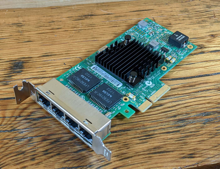
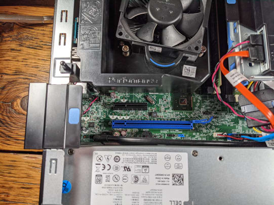
By default, this computer only has one RJ45 Ethernet port. However, if this is going to serve as a firewall, it will need at least two Ethernet ports. To achieve this, I purchased an Intel i350 network card which comes equipped with four Ethernet ports. The i350 network card is designed to be used in the four-lane PCIe slot on the desktop’s motherboard.
For this SFF chassis, I had to swap out the full-frame-sized metal bracket with the included smaller bracket on the network card. Then simply open the chassis and flip open the external clamp covering the empty PCI slots. With a screwdriver, you can remove the blank metal bracket insert in front of the four-lane PCI slot and insert the network card. Then, close the clamp and put the chassis side-cover back on.
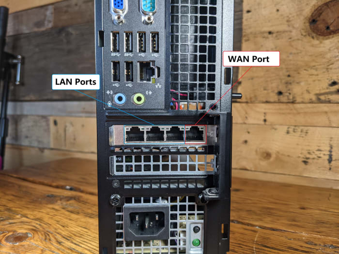
Once installed, it is important to note which Ethernet port is for the wide area network (WAN) and which ports are for the local area network (LAN). WAN is what faces out to the wide open public internet and LAN is what faces in to your local home network.
Once installed, you can set your desktop computer to the side for now. You will want to use your network-connected computer to download and verify the pfSense image and flash it to a USB drive.
Step Two: How To Download And Verify The pfSense Image File And Flash It To A USB Drive
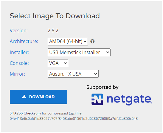
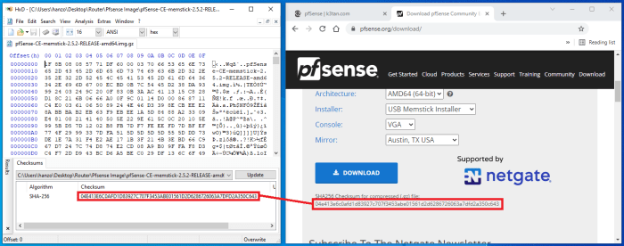
First, navigate to this pfSense download page and, once there:
- Select the “AMD64” architecture
- Then “USB Memstick installer”
- Then “VGA” console
- Then select whichever mirror is closest to your geographic location, such as demonstrated in the screenshot below, and click on “Download”
Next, you can calculate the SHA-256 checksum on the compressed file you downloaded and verify it against the checksum displayed on the pfSense download page.
I like to use a freeware hex editor called HxD for calculating checksums. Just open the file you are interested in, navigate to “Tools” then “Checksums” and select “SHA256” from the menu. If the hash values don’t match, do not run the executable file.
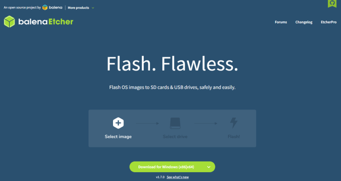
The easiest way I have found to flash an image file to a USB drive is to use a program called balenaEtcher.
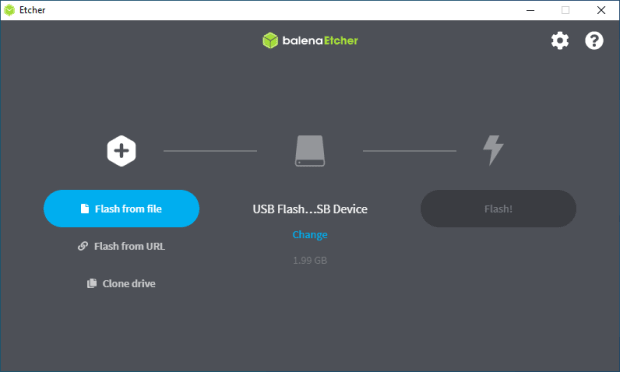
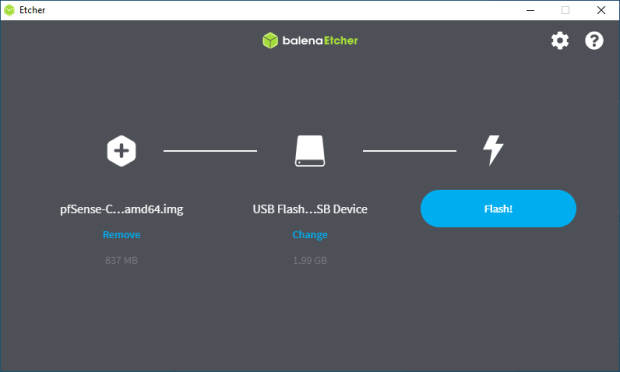
Once installed, launch the application, click on “Flash from file,” then navigate to the folder where you have the compressed pfSense image file.
Next, select your blank USB drive and then click on “Flash.” BalenaEtcher will begin the flashing process and automatically decompress the pfSense image file. This process will take a few minutes.
After the flashing is complete, you should get a green check mark indicating that everything checks out. If you get an error from balenaEtcher, you may need to try flashing to a different USB drive.
Now you can safely eject the flashed USB drive from your computer and you are ready to flash the other desktop computer.
Step Three: How To Flash The Desktop And Install pfSense
Connect a keyboard, monitor, power cable and the flashed USB drive to your desktop computer that you installed the network card in. The monitor needs to be connected via VGA connections — DisplayPort connections won’t work in my experience. Do not connect the Ethernet cables yet.
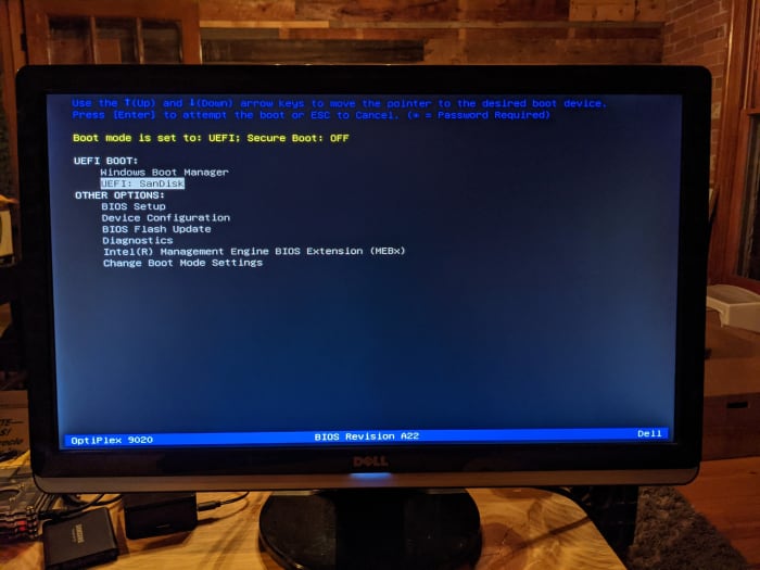
Once everything is connected, power on your desktop. Some computers will automatically detect that there is a bootable USB drive inserted and they will ask you which drive you want to boot from. In my case, the computer just defaulted to booting from the “C:” drive and launched Windows automatically. If this happens to you, shutdown the computer and then hold down “F12” on the keyboard and turn it back on. This will launch the BIOS, where you can tell the computer which drive you want to boot from.
For example, here is my BIOS environment where I was able to select the SanDisk USB drive that I had flashed the pfSense image to. After selecting this option, a script will run briefly and then the pfSense installer will launch:
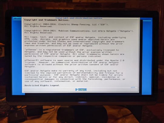
First, accept the terms and conditions. Then select “Install pfSense,” then choose the keymap appropriate for you. If you speak English and live in the U.S., you will probably just want to use the default.
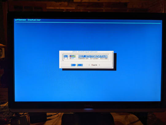
Next, I just chose the “Auto ZettaByte File System” (ZFS) option because I’m using a hardware platform that is way over spec’d for a home firewall. The ZFS option has more features and is more reliable than the Unix File System (UFS) option, but ZFS can be more memory hungry, which I’m not really concerned with given that I have 16 GB of RAM in this desktop.
Then, you will have some partitioning and redundancy options, which I just kept as simple as possible, e.g., no redundancy and the default configuration options. Then, select “Install.”
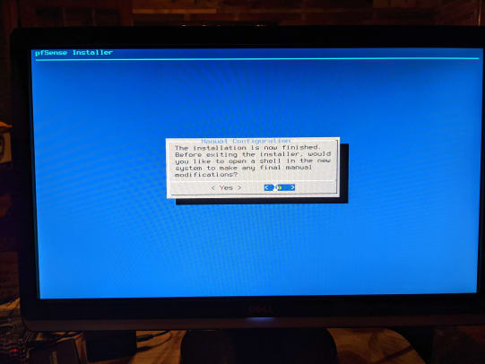
Then, you will see a couple of confirmations that the pfSense installation was successful. A prompt will ask you if you want to manually make any final modifications, which I did not. Then, it will ask you if you want to reboot, select yes. Immediately remove the USB drive at this time before the reboot kicks back on because otherwise it will drop you at the beginning of the installation wizard again. You should wind up at the main terminal menu once the reboot is finished.
Now you are ready to connect your new firewall to your home network.
Step Four: How To Connect The pfSense In A Home Network
The following steps will all be completed on the keyboard and monitor connected to your new firewall:
- First, power off your ISP-provided router, power off your modem and disconnect the Ethernet cables from your modem and router.
- Next, power on your new firewall and let pfSense load. Then, power on your modem and wait for it to link to the internet.
- In the pfSense menu, select option one, “Assign Interfaces.” It will ask you if you want to set up VLANs now, enter “n” for no. Then it will ask you to enter the WAN interface name, enter “a” for auto-detect.
- Connect an Ethernet cable from your modem output to your new firewall network card interface. Remember, the port on the far-right side if the RJ45 release tabs are facing up is your WAN port, or the far-left side if the RJ45 release tabs are facing down.
- Once connected, hit “enter.” It should detect link-up on interface port igb0. If it is igb3, then switch the Ethernet cable to the opposite side and try again.
- Then it will ask you to enter the LAN interface name, enter “a” for auto-detect. Connect an Ethernet cable from the next available port on the new firewall network card to your Ethernet switch or other access point. Keep in mind that if you intend on running a Virtual Local Area Network (VLAN), you will need to use a managed switch.
- Once connected, hit enter. It should detect link-up on interface port igb1.
- Then, hit enter again for “nothing” as no other network connections are configured at this time.
- Then it will inform you that the interfaces will be assigned as follows: WAN = igb0 and LAN = igb1.
- Enter “y” for yes and pfSense will write the configuration and bring you back to the main menu with your WAN IP v4 and IP v6 addresses displayed on top.
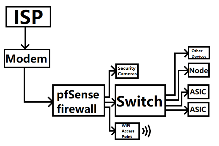
Just to illustrate an example signal path configuration, you could do a setup like this:
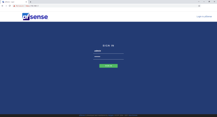
At this point, you should be able to enter “192.168.1.1” into your web browser on your regular desktop and launch the pfSense web interface. It is a self-signed certificate, so accept the risk when prompted and continue. The login credentials are admin/pfsense.
You can now disconnect the keyboard and monitor from your new firewall. The rest of the steps will be completed through the web interface on your regular desktop.
Step Five: How To Configure The pfSense Basic Settings
In this step, you will see how to configure basic settings like the setup wizard, change the TCP port, enable Secure Shell SSH, and set up hairpinning by default. The vast majority of the information presented here and in step six below came from watching this Tom Lawrence video on pfSense — I highly recommend watching this video, it is lengthy but packed full of valuable information and has way more details than I present in this guide.
First, click on the red warning dialog at the top of the page to change the password used to log into your new firewall. Personally, I recommend high-entropy, single-use passwords with an accompanying password manager. Then, log out and log back in to test your changes.
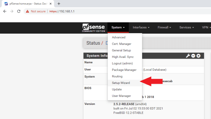
Once logged back in, open the “Setup Wizard” from the “System” tab:
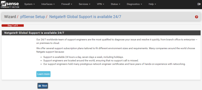
Then, the wizard will walk you through nine basic steps to get your new pfSense firewall configured.
Click “Next” on the first step.
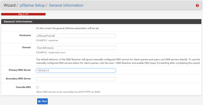
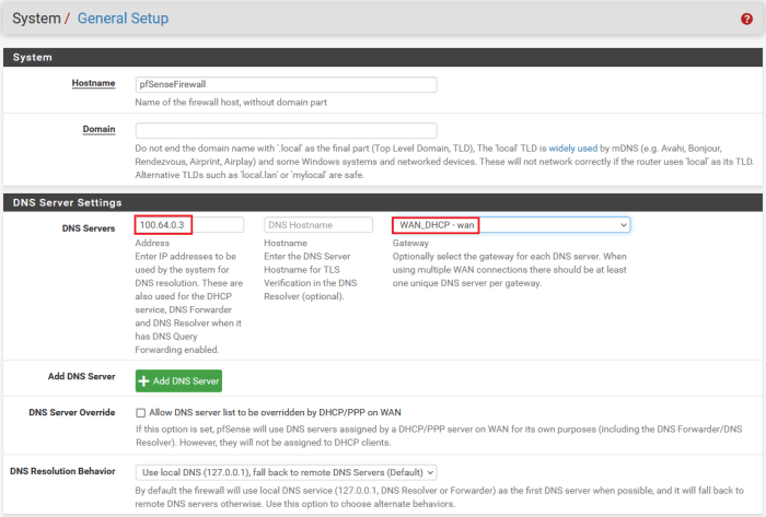
Then, on the second step, you can configure the hostname, domain and primary/secondary DNS servers. You can leave “Hostname” and “Domain” as their defaults or set them to whatever you want. I chose “100.64.0.3” for the primary DNS server for getting out to the internet and unchecked the “Override DNS” box to avoid having DHCP override the DNS servers. I’ll go over why I used “100.64.0.3” in step 10 of this guide.
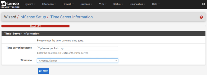
Then, you can set your timezone in step three:
On the fourth step, you can select “DHCP” for the WAN interface and leave all of the other fields as their defaults. If you want to spoof your MAC address, you can do so in this step. For the last two fields, ensure the “Block RFC1918 Private Networks” box and the “Block bogon networks” box are checked, this will automatically add the appropriate rules to your firewall.
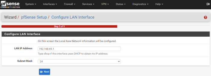
In step five, you can change your firewall’s IP address. Most home local networks will either use 192.168.0.1 or 192.168.1.1 to access the router or firewall. The reason you may want to change this to a non-default local IP address is because if you are on someone else’s network and you are trying to VPN back into your home network, then you may run into an issue where you have the same address on both ends and the system won’t know if you are trying to connect to the local or remote address. For example, I changed my local IP address to “192.168.69.1.”
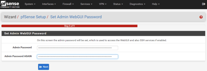
In step six, you can set your admin password. I was a little confused to see this step inserted here since I had changed the admin password at the beginning, so I just used my same high-entropy password from before, assuming it was asking for the same password that will be used to log into the router.
Then, in step seven, you can click the “Reload” button. As this is reloading, unplug the power cable from your switch. Since the router local IP address was changed to “192.168.69.1” (or whatever you chose), all the devices on the network will now have their IP addresses updated to that IP range.
So, if you have PuTTY or other SSH sessions configured to your Raspberry Pi node for example, you will now need to update those connection configurations. Unplugging the power from the switch and plugging it back in after the router is rebooted helps get all your devices reassigned.
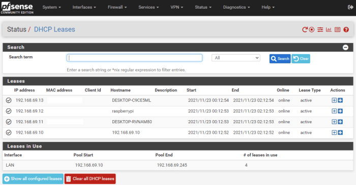
To figure out the IP addresses for the devices on your local network, you can navigate to the “Status” tab and select “DHCP Leases” to see everything listed out:
After the reload in step seven, the wizard just skipped over steps eight and nine, so I’m not sure what happens in those steps, but we will move on and address things as necessary.
A couple of other basic settings worth noting are found under “System>Advanced>Admin Access.” Here, I updated the TCP port to “10443” because I run some services that will access the same default ports like 80 or 443 and I want to minimize congestion.
Also, I enabled SSH. Then, you can choose how SSH is secured, either with a password, or keys, or both or keys only. Upon saving, give the interface a minute to update to the new port. You may need to reload the page using the local IP address and the new port, e.g., “192.168.69.1:10443.” Make sure to save your changes at the bottom of the page.
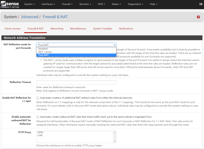
The last basic setting I’ll cover here is hairpinning, which means that, for example, you can have your network setup so that you can open a port to a security camera system with a public IP address. This public IP address can also be used inside your network too, which is convenient if you are at home accessing the camera system from your mobile phone on your LAN then you don’t have to manually change where it connects to, because hairpinning will see that you are just trying to access a local IP and it will loop you back around by default with this setting enabled.
- Under the “System” tab, navigate to “Advanced>Firewall & NAT”
- Scroll down to the “Network Address Translator” section
- From the “NAT Reflection Mode” drop-down menu, select “Pure NAT”
- Click “Save” at the bottom of the page and “Apply Changes” at the top of the page
That is it for the basic settings. The good news is that pfSense is rather secure in it’s default installation so there is not a whole lot you need to change to have a great basic foundation. Generally, the position of the pfSense developers is that if there is a more secure way to roll out pfSense, then they will just make that the default setting.
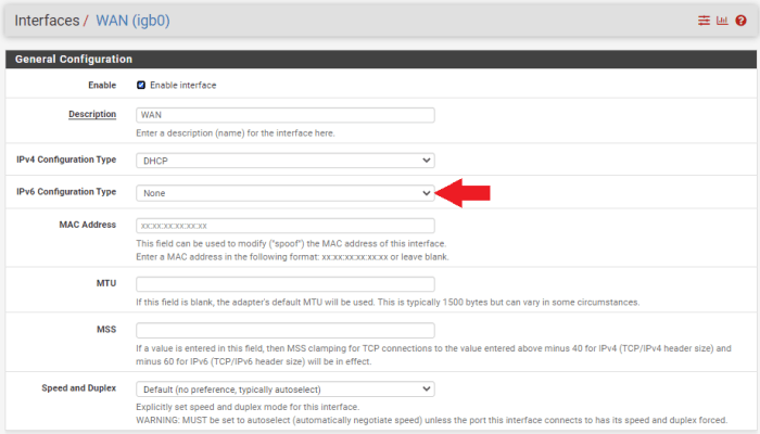
One other thing to note is that by default, pfSense enables WAN IPv6 network address translation (NAT) mapping. I chose to disable this, so I’m not opening up an IPv6 gateway to the wide-open internet.
You can do this by going to “Interfaces>Assignments” and then clicking on the “WAN” hyperlink on the first assignment. This will open up the configuration page, then just make sure that the “IPv6 Configuration Type” is set to “None.” Then save and apply those changes.
Then you can navigate to “Firewall>NAT” and scroll down to the “WAN” interface with an IPv6 source and delete it.
Step Six: How To Configure The pfSense Advanced Settings
In this section I will go over some advanced features that you may be interested in for your home network. Here, you will see how to set up separate networks from your pfSense router so that, for example, guests can access the wide-open internet from a WiFi access point in your home but they cannot access your ASICs from that network.
If you used the i350 network card like I did then you have four Ethernet ports available, and if you used a Dell Optiplex like I did then you also have a fifth Ethernet port on the motherboard. Which means that I have five interfaces I can configure, four of which can be secondary local networks.
What I am going to do here is keep my work desktop and my dedicated Bitcoin desktop on one network (LANwork). Then, I will configure a secondary LAN that my home’s WiFi access point will be on (LANhome). This way, I can keep traffic from my family’s web browsing totally separate from my work and Bitcoin-related activities.
Then, I will set up another LAN which will be dedicated for my ASICs (LANminers), separate from the other two networks. Finally I’ll create a test network (LANtest) which I will use to integrate new ASICs and ensure there is no malicious firmware on them before exposing my other ASICs to them. You could also add a security camera network on one of the interfaces, the possibilities are endless.
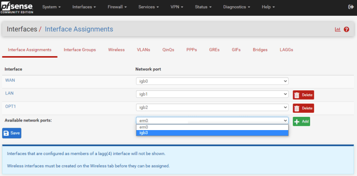
If you navigate to the “Interfaces” tab, then “Interface Assignments,” you will see all of your available network card RJ45 ports. They should be labeled “igb0,” “igb1,” “igb2,” etc. Now, simply add the one you are interested in by selecting it from the drop-down menu and clicking on the green “Add” box.
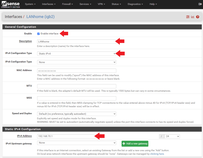
Then, click on the hyperlink on the left-hand side of the interface you just added to open up the “General Configuration” page for that interface.
- Click the “Enable Interface” box
- Then, change the “Description” to something that helps identify its function, like “LANhome,” for example
- Then, set the “IPv4 Configuration” type to “Static IPv4” and assign a new IP range. I used “192.168.69.1/24” for my first LAN so for this one, I will use the next sequential IP range, “192.168.70.1/24.”
You can leave all of the other settings on their defaults, click “Save” at the bottom of the page and then “Apply Changes” at the top of the page.
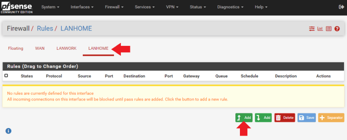
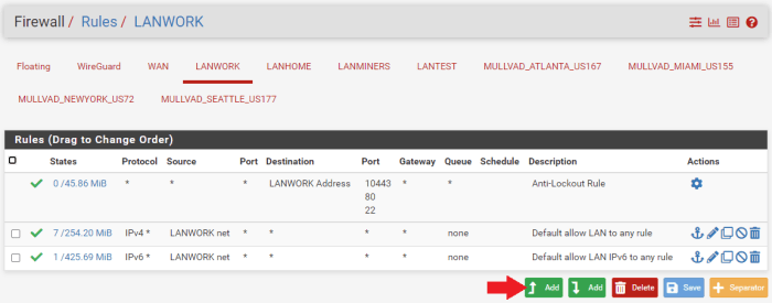
Now, you need to set up some firewall rules for this new LAN. Navigate to the “Firewall” tab, then “Rules.” Click on your newly-added network, “LANhome,” for example. Then, click on the green box with the up arrow and the word “Add.”
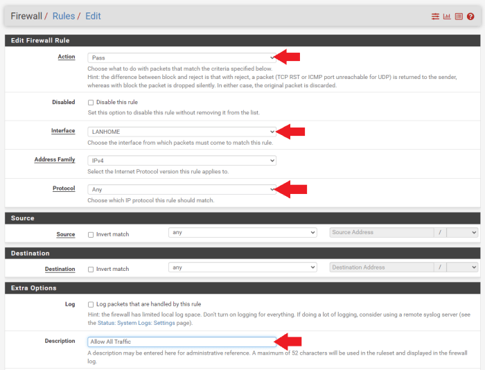
On the next page:
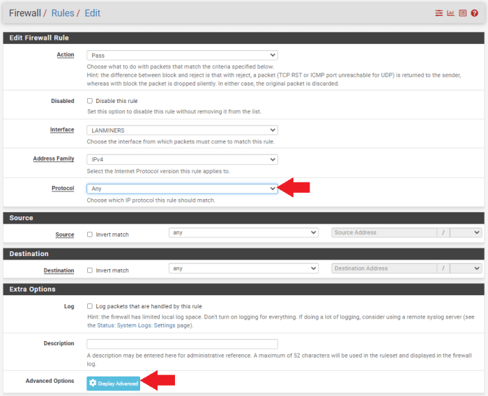
- Make sure the “Action” is set to “Pass”
- The “Interface” is set to “LANhome” (or whatever your secondary LAN is called)
- Be sure to set the “Protocol” to “Any” otherwise this network will restrict the type of traffic that can be passed on it
- Next, you can add a short note to help indicate what this rule is for, such as “Allow All Traffic”
- Then all other settings can remain in their defaults and click “Save” at the bottom of the page and “Apply Changes” at the top of the page
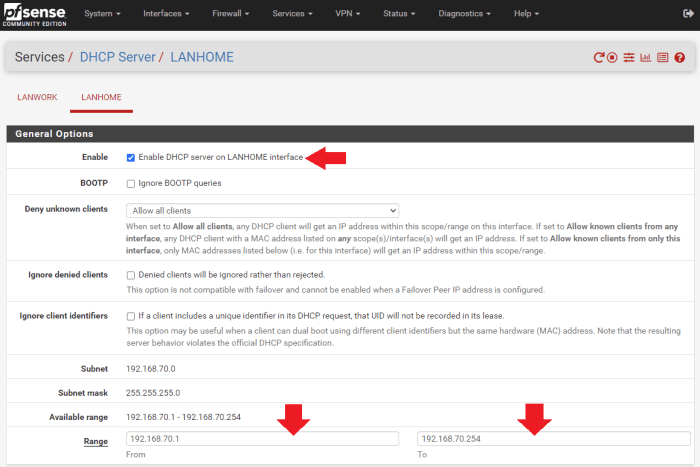
Before you can test your new network, you need to have an IP address set up on it:
- Navigate to “Services,” then “DHCP Server”
- Then click on the tab for your new LAN
- Click on the “Enable” box and then add your IP address range in the two “Range” boxes. For example, I used the range from “192.168.70.1 to 192.168.70.254.” Then, click on “Save” at the bottom of the page and “Apply Changes” at the top of the page.
Now you can test your new network by physically connecting a computer to the corresponding RJ45 port on the network card and then try to access the internet. If everything worked, then you should be able to browse the wide-open web.
However, you may notice that if you are on your secondary LAN and you try to log into your firewall, you will be able to do so using the “192.168.70.1” IP address. Personally, I only want my firewall accessible from my “LANwork” network. I do not want my wife and kids or guests to be able to log into the firewall from their designated “LANhome” network. Even though I have a high-entropy password to get into the firewall, I am still going to configure the other LANs so that they cannot talk to the router.
One area of concern I have, that this kind of configuration will help alleviate, is if I plug an ASIC into my network with some malicious firmware installed on it, I can keep that device isolated and prevent that security concern from affecting other devices and information that I have, which is why one of the LANs I am setting up is called “LANtest,” which will be dedicated to keeping new ASICs totally isolated so I can test them in safety without allowing a potential attack to occur on my other ASICs or other devices on my home’s networks.
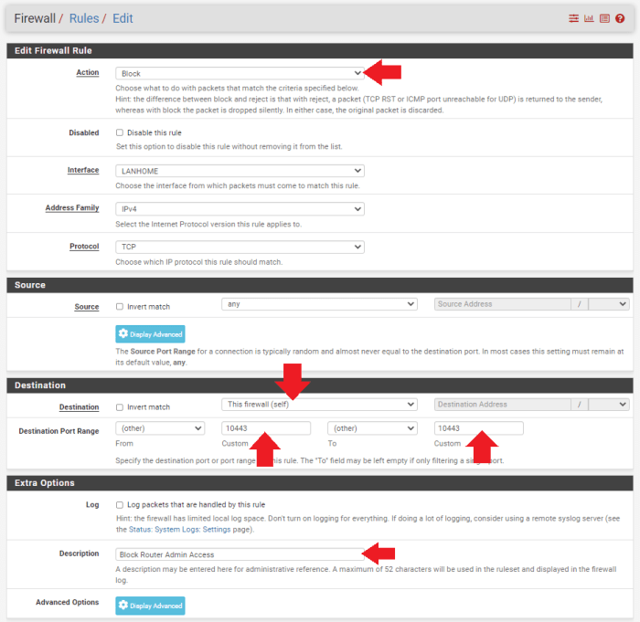
To set up a rule so that port 10443 cannot be accessed from your other LAN networks, navigate to “Firewall>Rules” and then select the tab for your corresponding network of interest. Click on the green box with the up arrow and word “Add” in it.
- Make sure “Action” is set to “Block”
- Then, under the “Destination” section, set the “Destination” to “This Firewall (self)” and then the “Destination Port Range” to “10443” using the “Custom” boxes for the “From” and “To” fields
- You can add a description to help you remember what this rule is for. Then click on “Save” at the bottom of the page and then “Apply Changes” at the top of the page.
Having a high-entropy password to log into the router and locking down the port is a great start, but you can further sequester your LAN networks and ensure that devices on one network cannot get onto any of the other networks at all by setting up an alias for your primary LAN.
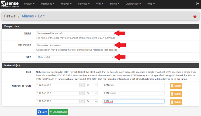
Navigate to “Firewall>Aliases,” then under the “IP” tab click on the “Add” button.
- Then, I named this alias “SequesteredNetworks0”
- I entered a description to remind me of what it’s function is
- Since I will be adding a firewall rule to my “LANhome” network referencing this alias, I added the other LANs to the “Network” list. This way, “LANhome” cannot talk to “LANwork,” “LANminers” or “LANtest.”
- Click on “Save” at the bottom of the page and then “Apply Changes” at the top of the page
Now I can add additional aliases that will be referenced in firewall rules on the other LANs to prevent “LANminers” from talking to “LANwork,” “LANhome,” and “LANtest” — so on and so forth until all my networks are sequestered in a way that only my firewall can see what is connected on the other networks.
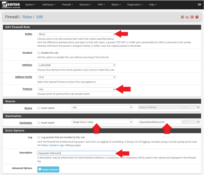
With the alias created, a new firewall rule can be applied referencing this alias on the secondary LAN.
- Navigate to “Firewall>Rules,” select the LAN you want to apply the rule to, e.g, “LANhome”
- Then for “Action” set it to “Block. For “Protocol” set it to “Any.”
- For “Destination” set it to “Single host or alias”
- Then enter your alias name
- Click on “Save” at the bottom of the page and then “Apply Changes” at the top of the page.
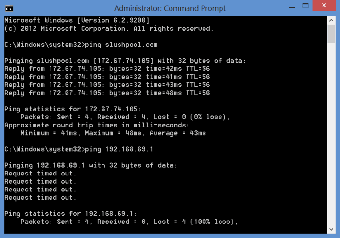
Once I created the aliases and set the firewall rules, I was then able to connect my laptop to each network card RJ45 interface port and attempt to ping each of the other networks. I could get out to the wide-open internet from each LAN but I was not able to communicate with any of the other LANs or the firewall. Now I know any devices on any of my LANs will not have access to devices on any of my other LANs. Only from my primary “LANwork” network am I able to see what is connected on all of the other LANs.
That takes care of the advanced features that I wanted to share with you. You should now have some firewall rules set up and multiple networks sequestered. Next, we’ll get into setting up a WiFi access point on one of the secondary LANs.
Step Seven: How To Set Up And Configure A WiFi Access Point
In this section I’ll show you how I configured my home’s mesh WiFi using the secondary “LANhome” network. The key points to keep in mind here is that I made this a dedicated LAN specifically for a WiFi access point for my family and guests to link to without giving them access to my pfSense firewall or any other LANs. But they still have unrestricted access to the wide-open web. I will add a VPN tunnel for this LAN later in this guide.
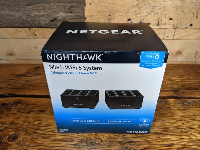
To ensure that I was providing adequate WiFi signal to the entire house, I decided to go with a NetGear Nighthawk AX1800 kit.
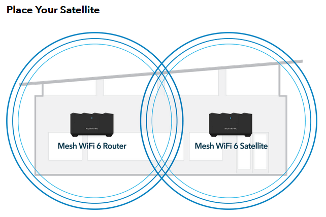
Inside this kit is a WiFi router and a repeater satellite. The basic idea is that the WiFi router gets connected to the pfSense firewall directly with an Ethernet cable on the igb2 “LANhome” port. Then, the WiFi router broadcasts the signal to the repeater satellite in another area of the house. Like this, I can increase the WiFi signal coverage to a wider area.
To accomplish this I simply followed these steps:
- 1. Plug the WiFi router in the pfSense firewall on port igb2 “LANhome” using an Ethernet cable to the port labeled “Internet” on the back of the WiFi router.
- 2. Plug a laptop into the port labeled “Ethernet” on the back of the WiFi router with an Ethernet cable.
- 3. Plug the WiFi router into power using the supplied power adapter.
- 4. Wait for the light to turn solid blue on the front of the WiFi router.
- 5. Open a web browser on the laptop and type in the IP address for the WiFi router. I found the IP address next to the “MR60” device in my pfSense dashboard under “Status>DHCP Leases.”
- 6. Immediately, I was prompted to change the password. Again, I used a high-entropy, random password with an accompanying password manager. I don’t want my family or guests to be able to access this WiFi access point administrative settings, so placing a strong password here is recommended. You may also be prompted to update the firmware as well, which will result in a reboot.
- 7. Then, you can log back in with your new admin password and change the default network name to whatever you want and add a WiFi password to access the WiFi network; this is the password shared with family and guests so this one I made pretty easy to remember and share. Even if a nefarious actor cracks the password and gains access to the WiFi network, it is totally sequestered from everything else and the WiFi router itself has a high-entropy password.
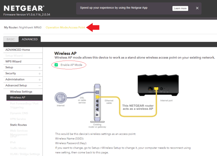
- 8. Then, navigate to “Advanced>Wireless AP” and enable “AP Mode.” “AP” stands for access point. Then, apply the changes.
- 9. The router will reboot again. At this point, the local IP address will be updated, this change can be monitored in the “DHCP Leases” status page. Now, the laptop can be unplugged from the WiFi router and the WiFi router can be logged into from the same machine as the pfSense interface is running.
- 10. Once logged in again, click on “Add Device” and you will be prompted to set the satellite repeater in place and connect it to power. Then follow the prompts on the interface to sync the satellite.
Now my family, guests and I can browse the wide-open web from our devices via WiFi with no dropouts in the whole house and I don’t have to be concerned with anyone accessing my sensitive work network, or my ASIC network or my test network.
Next, we’ll get into adding VPN tunnels to the networks we’ve created so far.
Step Eight: How To Install And Configure The WireGuard Package With Mullvad
WireGuard is a VPN software protocol that can be installed on your pfSense firewall, then you can use that protocol to define how you construct your tunnels with your VPN provider.
VPNs create a secure and encrypted tunnel from your computer to your VPN provider’s server. This prevents your ISP from seeing your data or where it’s final destination is. There are several types of VPN protocols, such as OpenVPN, IKEv2/IPSec, L2TP/IPSec and WireGuard, but they all essentially have the same goal to outline the instructions for creating a secure tunnel for encrypting your data to be sent over public networks.
WireGuard is a recent addition to the lineup of VPN protocols, it is open-source, and comparatively “light,” with less code and faster speeds than some others. The speed part was key for me considering that added latency can decrease an ASICs efficiency.
Another benefit of VPNs is that your geographic location can be spoofed, meaning that if you are in one part of the world, you can use a VPN tunnel to a VPN provider’s server in another part of the world and it will appear as though your internet traffic is coming from that server. This is beneficial for people who live in authoritative countries where access to certain websites and services is restricted.
Keep in mind that you have to trust that your VPN provider is not logging your IP address or that it could or would turn this information over to authorities if pressed. Mullvad collects no personal information about you, not even an email address. Plus, it accepts bitcoin or cash so you can pay for the service without the risk of linking your banking details. Mullvad also has a “no-logging” policy, which you can read here.
For my specific use case here, I will be using a VPN to ensure my ISP does not see that I am mining Bitcoin and to also prevent my mining pool, Slush Pool, from seeing my real IP address — not because I am doing anything illegal or because I think Slush Pool is logging my IP address, but simply because these are tumultuous times with a quickly-changing political environment and the things I do legally today could very well be outlawed tomorrow.
Or, if some legislation was passed making it illegal for a person to operate a Bitcoin miner in the United States without a money transmitter’s license, for example, then I could spoof my location so that if Slush Pool’s hand were forced to block IP addresses coming from the United States, I could continue mining as it would appear my hash rate was originating from outside the United States.
Considering that the blockchain is forever and the future is uncertain, I think it is worth taking the time to figure out how to guard my privacy. By taking steps today to increase my privacy and security, I can ensure that my freedom and my pursuit of happiness are guarded.
The vast majority of the information presented in this section comes from watching Christian McDonald videos on YouTube. You can find all of his WireGuard & Mullvad VPN videos here.
I want to specifically point out this video of his on using the WireGuard package in pfSense to set up Mullvad in a way to have multiple tunnels that allow load balancing your traffic seamlessly:
Mullvad is a paid VPN subscription, the fee is €5 per month. However, Mullvad does accept bitcoin and does not require any identifying information. Before I show you how to set up your Mullvad subscription, we’ll get the WireGuard package installed to your pfSense firewall. Then, we’ll set up a Mullvad account and generate the configuration files. Then, we can get multiple tunnels set up and do some fancy configurations in pfSense.
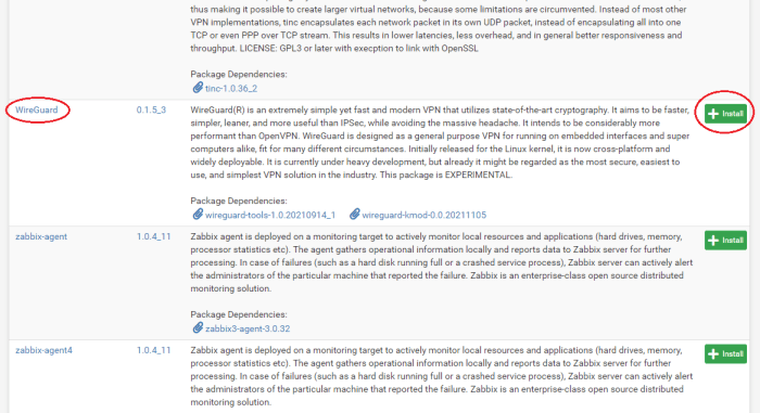
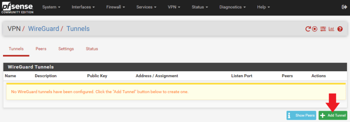
In pfSense, navigate to “System>Package Manager>Available Packages” then scroll down to the WireGuard link and click on “Install.” On the next page, click on “Confirm.” The installer will run and let you know when it has successfully completed.
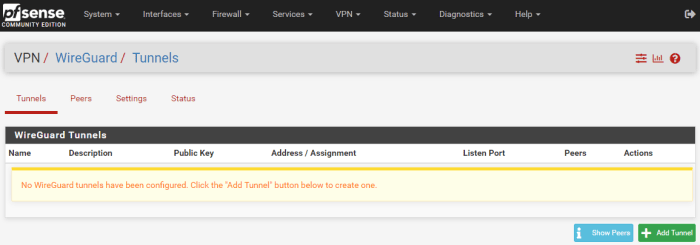
Now, you can navigate to “VPN>WireGuard” and see that the package has been installed but nothing is configured yet. Now that the firewall has WireGuard ready, we will work on getting the VPN client installed.
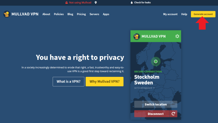
Navigate to https://mullvad.net/en/ and click on “Generate Account.”
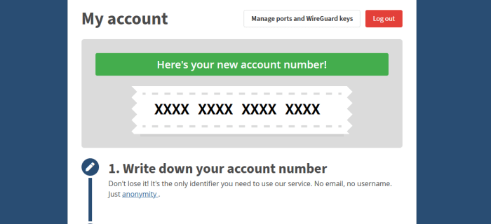
Mullvad does not collect any information from you such as name, phone number, email, etc. Mullvad generates a unique account number and this is the only identifying piece of information you get related to your account, so write it down and secure it.
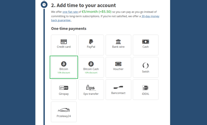
Next, select your payment method. You get a 10% discount for using bitcoin. The subscription works for as long as you want to pay for (up to 12 months) at the rate of €5 per month. So, a one-year subscription for example would be €60 or about 0.001 BTC at today’s rate (as of November 2021). You will be presented with a Bitcoin address QR code to send your payment to.
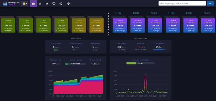
Check the mempool to see when your Bitcoin transaction gets confirmed. You may need to wait a while depending on network congestion.
After confirmation on chain, the Mullvad account is topped off and should show that you have time remaining. Make considerations about selecting a server location from Mullvad’s long list of servers. If you’re planning on running ASICs behind your VPN, then I recommend connecting to a server relatively close to your actual geographic location to try and help reduce any latency as much as possible.
The way Mullvad works is with configuration files that assign a unique public/private key pair for each tunnel address. The basic idea here is that I want to have a primary tunnel set up for the ASICs, but I also want a secondary tunnel setup with another server in a different geographic location just in case the primary tunnel connection goes offline. This way, my mining internet traffic will automatically switch over to the other tunnel and there will be no interruption in concealing my public IP address or encrypting my traffic data. I’m also going to set up other tunnels specifically for my WiFi network and my “LANwork” network.
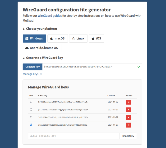
To do this, I will need as many key pairs as I want tunnels. One Mullvad subscription includes up to five key pairs. Navigate to https://mullvad.net/en/account/#/wireguard-config/ and select your platform, e.g, Windows. Then click on “Generate Keys” for as many key pairs as you want, up to five keys. Then click on “Manage Keys” below that to see your list.
*All keys and sensitive information presented in this guide have been nuked prior to publishing. Be cautious about sharing this information with anyone, you want to keep your Mullvad keys private.
You can see that I generated four keys for this guide, which I will destroy after I’m finished using them as examples. Each configuration file needs to be set up with a specific Mullvad server of your choosing.
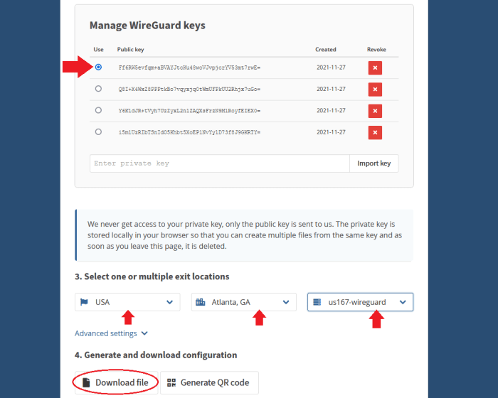
- Select the “Public Key” you are interested in creating a configuration file for by selecting the circle under the “Use” column next to the appropriate public key.
- Select the country, city and server you want to configure with this public key.
- Click on “Download File.”
- Save the configuration file in a convenient place because you will need to open it in a moment.
*Remember, for each tunnel to a new server you want to configure, you will need to use a separate public key. If you try to assign two tunnels to the same key, pfSense will encounter problems with your VPN.
Repeat this process for as many keys as you generated, selecting a different server for each unique key and generating the configuration file. I found it helpful to name the configuration file as the city and server used.
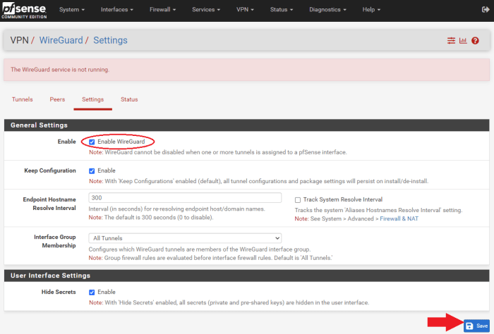
Now, navigate back to pfSense and go to “VPN>WireGuard>Settings” and click on “Enable WireGuard” and then “Save.”
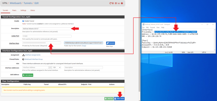
- Navigate to the “Tunnels” tab and select “Add Tunnel.”
- Open your first Mullvad configuration file with a text editor like Notepad and keep it to the side.
- In WireGuard, add a “Description” for your tunnel that describes what it is, like “Mullvad Atlanta US167.”
- Copy/paste the “PrivateKey” from the Mullvad configuration file and add it to the “Interface Keys” dialog box.
- Click on “Save Tunnel,” then “Apply Changes” at the top of the page.
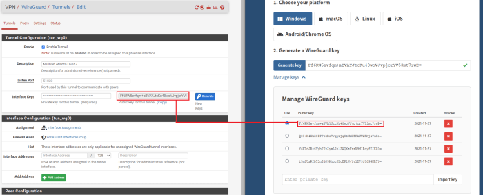
WireGuard will automatically generate the public key when you paste the private key and hit the “tab” key on your keyboard. You can verify that the public key was correctly generated by comparing it to the key on the Mullvad website that you generated earlier.
Repeat this process for as many tunnels as you want. Make sure you use the correct Mullvad configuration file for each one as they all contain different public/private key pairs, IP addresses, and endpoints.
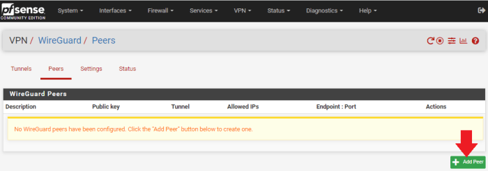
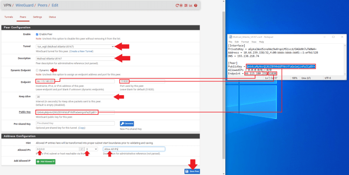
Each tunnel will get its own peer. You can add a “Peer” by first navigating to the “Peer” tab next to the “Tunnels” tab that you were just on. Then click on “Add Peer.”
- Select the appropriate tunnel from the drop-down menu for this peer.
- Add a “Description” for your tunnel that describes what it is, like “Mullvad Atlanta US167.”
- Uncheck the “Dynamic Endpoint” box.
- Copy/paste the “Endpoint” IP address and port from the Mullvad configuration file into the “Endpoint” fields in WireGuard.
- You can give 30 seconds to the “Keep Alive” field.
- Copy/paste the “PublicKey” from the Mullvad configuration file into the “Public Key” field in WireGuard.
- Change the “Allowed IPs” to “0.0.0.0/0” for IPv4. You can also add a descriptor like “Allow All IPs” if you want.
- Click on “Save,” then select “Apply Changes” at the top of the page.
Repeat this process for as many peers as you have tunnels. Make sure you use the correct Mullvad configuration file for each one as they all contain different public/private key pairs, IP addresses and endpoints.
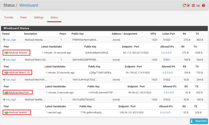
At this point, you should be able to navigate to the “Status” tab and observe the handshakes taking place by clicking on “Show Peers” in the lower right-hand corner.
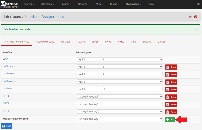
Next, the interfaces need to be assigned for each tunnel.
- Navigate to “Interfaces>Interface Assignments”
- Select each tunnel from the drop-down menu and add it to your list.
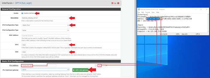
After all of your tunnels are added, click on the blue hyperlink next to each added tunnel to configure the interface.
- Click on the “Enable Interface” box
- Enter your description — I just used the VPN server name for example: “Mullvad_Atlanta_US167”
- Select “Static PIv4”
- Type “1420” in the “MTU & MSS” boxes
- Now, copy/paste the host IP address from your Mullvad configuration file in the “IPv4 Address” dialog box.
- Then, click on “Add A New Gateway”
After clicking on “Add A New Gateway,” you will be presented with the below pop-up dialog. Enter a name for your new gateway, something easy like the name of your tunnel appended with “GW” for “GateWay.” Then, enter the same host IP address from the Mullvad configuration file. You can also add a description if you want, such as “Mullvad Atlanta US167 Gateway.” Then click on “Add.”
Once you are back at the interface configuration page, click on “Save” at the bottom of the page. Then click on “Apply Changes” at the top of the page.
Repeat that process to create a gateway for each tunnel interface you added. Make sure you use the correct Mullvad configuration file for each one as they all contain different host IP addresses.
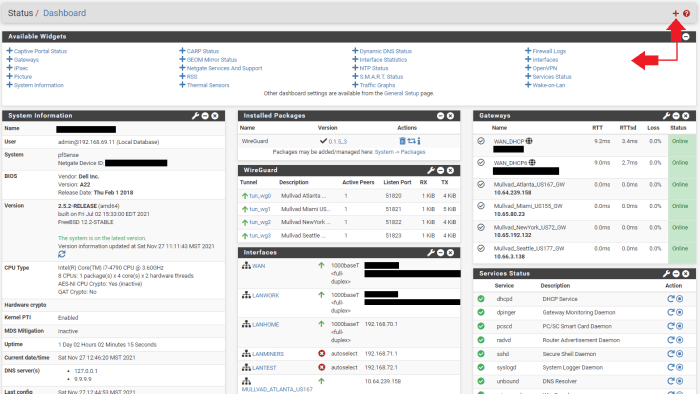
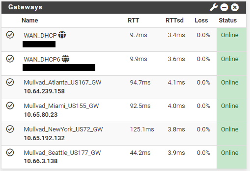
At this point, you can navigate to your dashboard and monitor the status of your gateways. If you have not done so already, you can customize your dashboard to monitor several stats in pfSense. Click on the “+” sign in the upper right-hand corner of your dashboard and then a list of available stat monitors will drop down and you can select the ones you want.
On my dashboard, for example, I have three columns, starting with the “System Information.” In the second column, I have the “Installed Packages” summary, “WireGuard” status, and a list of my interfaces. In the third column, I have the “Gateway” status and “Services” status. This way, I can quickly check and monitor the status of all sorts of things.
What I want to point out about the dashboard is that in the “Gateways” section, you will notice that all of the gateways are online. The gateways will be online so long as the tunnel is active, even if the remote side is not responding. This is because they are the local interface, so right now they are useless since even if the remote side goes down, they will still show as online. In order to enable the ability to monitor latency so that these gateways can provide some useful stats, I need to give these gateways a public domain name system (DNS) address to monitor.
You’ll notice that all the tunnel ping times are zero milliseconds. That’s because I’m not sending any data out through these tunnels. By pinging a public DNS server, pfSense can get some useful metrics and make decisions about which tunnel will provide the least latency or if a remote server goes down to reroute traffic.
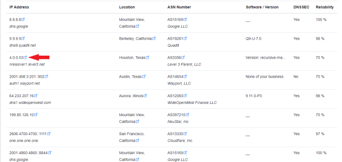
You can find a public DNS server to monitor at this website or a number of other public DNS server listings. Watch for the recorded uptime percentage, the more the better. You want to find public DNS IPv4 IP addresses to monitor on your IPv4 gateways. Each gateway will need a separate DNS address to monitor.
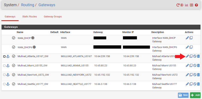
Once you have your public DNS addresses, navigate to “System>Routing>Gateways” in pfSense. Click on the pencil icon next to your gateway. You can see that the “Gateway Address” and the “Monitor IP” address are the same on all the gateways. That is why the ping time is zero milliseconds and this is also why pfSense will think the gateway is always up.
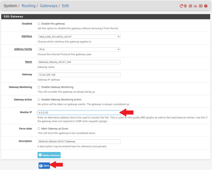
Enter the public DNS IP address that you want to monitor in the “Monitor IP” field and then click on “Save” at the bottom of the screen. Then click on “Apply Changes” at the top of the screen. Remember, gateways cannot share the same DNS monitor address so use a different public DNS server for each gateway to monitor.
Now, if you go back to your dashboard and look at your gateway monitor, you should see that there are some actual latency metrics to observe. With this information, you can set up your gateways in order of priority based on which ones have the lowest latency for your internet traffic. So, for example, if you are mining Bitcoin, then you will want to prioritize your ASICs to go through the tunnel with the lowest latency first. Then if that tunnel fails, the firewall can automatically switch them to the next tier gateway with the second to smallest latency and so on.
Everything is looking good so far, the tunnels are active and there is data going through the gateways. Next, we need to define some outbound network address translation (NAT) mapping on the firewall.
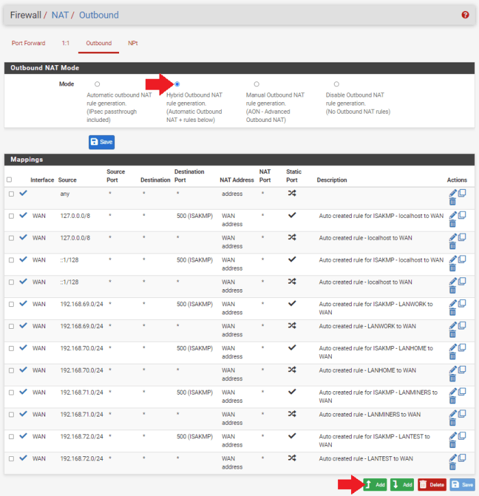
- Navigate to the “Firewall” tab, then “NATm” then the “Outbound” tab. This will pull up a list of all your network mappings from your WANs to your LANs. Since we have some new interfaces defined, we want to add these mapping to the list.
- Click on “Hybrid Outbound NAT Rule Generation” under the “Outbound NAT Mode” section.
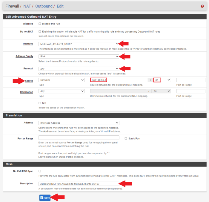
- Scroll to the bottom of the page and click on “Add”
- Choose your interface from the drop-down menu
- Select “IPv4” for the “Address Family”
- Select “any” for the “Protocol”
- Make sure “Source” is on “Network” and then enter the local IP address range for the LAN you want going down this tunnel. For example, I want my “LANwork” going through this tunnel to Atlanta, so I entered “192.168.69.1/24.”
- Then, enter a description if you want, such as “Outbound NAT for LANwork to Mullvad Atlanta US167.”
- Then, click on “Save” at the bottom of the page and “Apply Changes” at the top of the page.
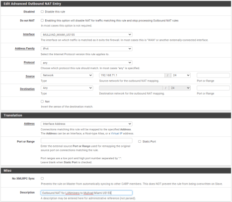
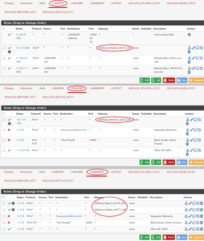
Repeat this process for each of the tunnel interfaces. You will notice that I have my “LANwork” network going to the Atlanta tunnel, my “LANhome” network going to the New York tunnel, and I have “LANminers” network set up for both the Miami and Seattle tunnels. You can set a mapping for your mining LAN to all five of your tunnels if you want. You can also have multiple LANs mapped to the same tunnel if you want, there is a lot of flexibility.
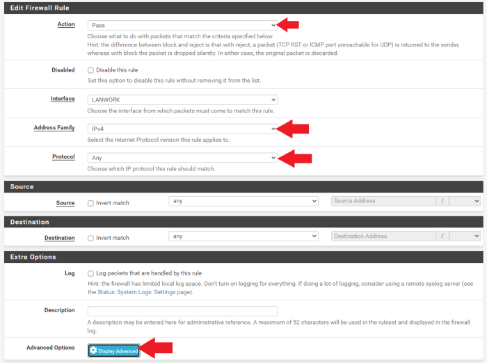
With the mappings all in place, we can add firewall rules. Navigate to “Firewall>LAN,” then click on “Add,” “LAN” being whichever LAN you want to add a rule to. For example, I’m setting up my “LANwork” network in this screenshot:
- Set “Action” to “Pass”
- Set “Address Family” to “IPv4”
- Set “Protocol” to “Any”
- Then click on “Display Advanced”
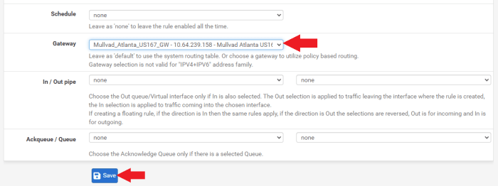
- Scroll down to “Gateway” and select the gateway you have set up for this LAN
- Click on “Save” at the bottom of the screen, then click on “Apply Changes” at the top of the screen
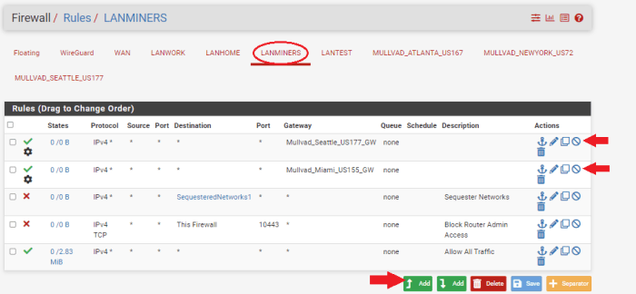
Then, do the same thing with your next LAN until you have all of your LANs set up with a gateway rule. Here is a snapshot of my LAN gateway rules, you’ll notice that I added two gateway rules to my “LANminers” network. In a later step, I will show you how to set up the automatic load balancing between tunnels for the mining LAN which will replace the two rules I just added to “LANminers,” but I want to make sure everything is set up and working correctly first.
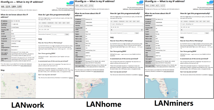
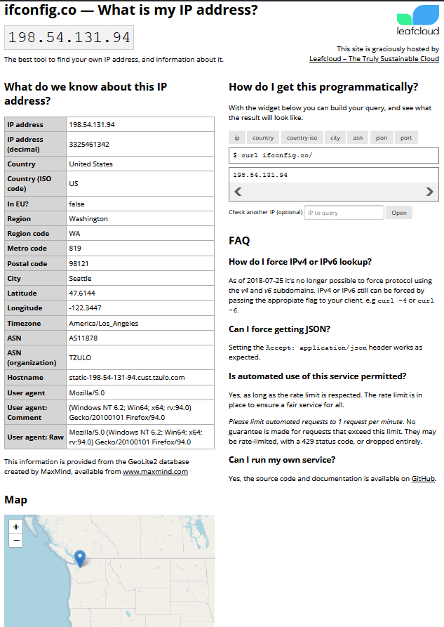
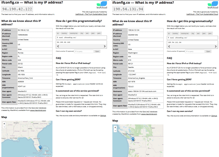
To double check that everything is working so far and that each of my LANs is getting different public-facing IPs, I will enter “ifconfig.co” into a web browser from each LAN. If everything is working correctly, then I should have different locations for each LAN I plug into and ping from:
Everything worked as planned, first try. While connected to each LAN, I was able to disable the corresponding firewall rule and refresh the page and watch my IP address change back to my actual rough geographic area.
If you recall, I had set up two tunnels for my “LANminers” network. When I disabled the one firewall rule corresponding to the Miami tunnel and refresh my browser, it immediately switched to an IP address in Seattle.
So, each LAN is sending traffic through a different tunnel and all of my tunnels are working as expected. However, in regards to my “LANminers” network, I want pfSense to automatically switch between the Miami and Seattle tunnels based on latency or downed servers. With a couple more steps, I can get this configured to switch automatically and replace the two firewalls rules with a new single rule.
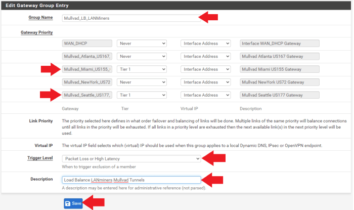
Navigate to “System>Routing” and then the “Gateway Groups” tab.
- Enter a group name like “Mullvad_LB_LANMiners.” The “LB” is for “Load Balance.”
- Set all of the other gateway priorities to “Never,” except the two gateways you are interested in for your miners. In this case, I’m using my Miami and Seattle gateways. I have those priorities both set to “Tier 1,” or you could use all five of your tunnels if you wanted.
- Set the trigger level to “Packet Loss or High Latency”
- Add a description if you want, such as “Load Balance LANminers Mullvad Tunnels”
- Click on “Save” at the bottom of the screen, then “Apply Changes” at the top of the screen
If you navigate to “Status>Gateways” and then the “Gateway Groups” tab, you should be able to see your new gateway group online. In theory, if you route traffic to “Mullvad_LB_LANminers” then it should balance traffic between the two gateways based on latency.
Now, this gateway group can be used in a firewall rule to policy route that traffic accordingly. Navigate to “Firewall>Rules” and then the “LANminers” tab or whatever your mining LAN is named.
Go ahead and disable the two rules you set up previously for testing the VPN tunnels by clicking on the crossed out circle next to the rule. Click on “Apply Changes,” then click on “Add” at the bottom.
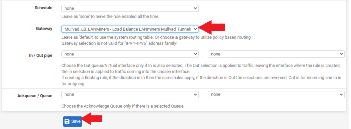
- Set the protocol to “Any”
- Click on “Display Advanced”
- Scroll down to “Gateway” and select the load balance gateway group you created
- Click on “Save” at the bottom of the page and click on “Apply Changes” at the top of the page
That should be all that is needed to get your ASICs to switch from one VPN tunnel to another VPN tunnel automatically based on latency or downed servers. To test this, plug a laptop into your dedicated Ethernet port on your network card for your mining LAN. This is “igb3” in my case.
Make sure your WiFi is off. Open a web browser and type “ifconfig.co” in the URL bar. The results should put you in the location of one of your VPN tunnels. In my case, it was Miami.
Then, back in pfSense, navigate to “Interfaces>Assignments” and click on the hyperlink for that tunnel interface. In my case, it is the “Mullvad_Miami_US155” interface.
At the very top of that configuration page, uncheck the box for “Enable Interface.” Then, click on “Save” at the bottom of the screen and then click on “Apply Changes” at the top of the screen. This has just disabled the Miami tunnel that my LANminers was sending traffic through.
Back on the laptop, refresh the browser with the ifconfig.co page. It should now be putting your location in Seattle, or wherever your secondary tunnel was set to. Sometimes, I have to completely close my browser and re-open it to clear the cache.
Make sure you go back to your Miami interface and re-check the box to enable that interface, then save, and apply. Then, you can navigate back to “Firewall>Rules,” then your mining LAN and delete the two rules you had disabled.
That’s it, you should be good to go. Keep in mind that firewall rules work in a top-down fashion. Next, I’ll get into how to help prevent ad tracking.
Step Nine: How To Configure Ad-Blocker Capabilities
Advertising companies are very interested in you and as much information as they can get about you. Unfortunately, when you browse the internet, it is easy to leak this sought after information.
This information is monetized to target specific audiences with products and services with surgical-like precision. You may have experienced doing an online search for something and then later noticed advertisements popping up in your social media feed that match your recent searches. This is made possible by gathering as much information about your internet searches, which websites you visit, which pictures you look at, what you download, what you listen to, your location, what’s in your shopping cart, what payment methods you use, the time and date of all this activity, then linking that information to uniquely-identifiable constants like the specific web browser you are using and on which device you are using it.
Combine this information with your IP address, ISP account and social media profile and you can start to see how there is a honeypot of information about you that you may not want so readily available to corporations, law enforcement, strangers or hackers. Between cookies, browser fingerprinting and behavioral tracking it can seem like the odds are stacked against you. But there are simple steps you can take to start guarding your privacy now. It would be a shame to allow perfect be the enemy of good and hold you back from getting started.
In this section, you will see how to incorporate ad-blocking capabilities by modifying the DNS server and DHCP server settings in your firewall. At a high level, you type a website name into your web browser, that gets sent to a DNS server (usually your ISP’s DNS server), and that server translates the human-readable text into an IP address and sends that back to your browser so it knows which web server you are trying to reach. Additionally, targeted ads are also sent to you this way.
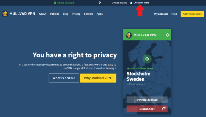
I recommend starting this exercise by visiting https://mullvad.net/en/.
Then, click on the “Check for leaks” link to see where you could improve.
If you get DNS leaks, depending on which browser you are using, you may find helpful instructions from Mullvad here to harden your browser and help prevent ad and tracking at the browser level. Then try again.
If you have problems blocking ads with your preferred browser, consider using a more privacy-focused browser like UnGoogled Chromium:
- Select your operating system and the latest version
- Download the installer .exe
- Verify the hash value
- Run the installer and then configure your basic settings like default search engine
Tor is another browser I would recommend to use as much as possible, just in general.
Mullvad provides a few different DNS-resolving servers that can be found listed in this Mullvad article. For this example, I will use the “100.64.0.3” server for the ad-tracker blocking. Make sure to refer to the Mullvad website for the latest updated DNS server IP addresses as these may change occasionally.
In pfSense, navigate to “System>General” then scroll down to the “DNS Server Settings” section and type “100.64.0.3” into the DNS Server field with your WAN gateway selected. If you used my recommendation from the beginning of the guide, then this should already be set but you will need to follow the DHCP instructions below.
Click on “Save” at the bottom of the page.
Next, navigate to “Services>DHCP Server” and scroll down to “Servers.” In the field for “DNS Servers,” enter “100.64.0.3” and click on “Save” at the bottom of the page. Repeat this step for all of your LANs if you have multiple networks setup.
Now you should have an ad-tracker blocking DNS server configured at the firewall level to help protect all of your internet browsing. Then, if you took the additional measures of configuring your web browser or upgrading to a privacy-focused web browser, then you have taken a big leap forward in guarding your privacy on your desktop devices.
I also recommend considering using UnGoogled Chromium or Bromite on mobile. If you are interested in more mobile devices privacy measures, check out my guide on CalyxOS here.
Step 10: How To Check For Latency Caused By The VPN
There is reasonable concern that using a VPN may introduce latency to your mining traffic. The problem with that is you will get fewer rewards.
When there is latency present, your ASIC may continue hashing a block header that is no longer valid. The longer your ASIC spends hashing an invalid block header, the more “stale” hash rate you will send to the pool. When the pool sees hashes coming in for a block header that is no longer valid, the pool rejects that work. This means that your ASIC just wasted some computing power for nothing, although this is on the scale of milliseconds, when an ASIC is calculating trillions of hashes every second, it can add up fast.
Typically, this is a very small ratio compared to the amount of work that is accepted by the pool. But you can start to see how significant and continuous latency could have an impact on your mining rewards.
Generally speaking, the closer two servers are to each other, the less latency there will be. With a VPN, I have to send my mining traffic to the VPN’s server and then from there it goes to the pool’s server. In an effort to try and mitigate latency by geographic proximity, I used three VPN servers that were between my location and the pool’s server. I also wanted to be cognizant of the risk in having a regional internet outage, so I also added two VPN servers that were not between the pool and me. With my “LANminers” network configured to load balance traffic between five different tunnels, I started a five-day test.
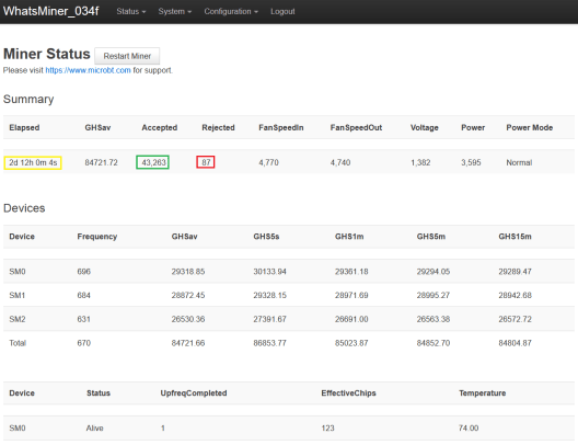
The first two-and-a-half days (60 hours) were spent mining with the VPN on. The second two-and-a-half days were spent mining with the VPN turned off. Here is what I found:
In the first 60 hours, my ASIC had 43,263 accepted packets and 87 rejected packets. This equates to 0.201%, or in other words, 0.201%, of my expended resources not being rewarded.
After 120 hours, my ASIC had 87,330 accepted packets and 187 rejected packets. By subtracting the initial 60-hour readings, I was left with 44,067 accepted packets and 100 rejected packets while the VPN was turned off. This equates to 0.226%. Surprisingly, this is slightly more of a rejection ratio without the privacy benefits of a VPN given the same amount of time.
In conclusion, by balancing my mining traffic between five VPN tunnels, I was able to gain the privacy benefits of a VPN without reducing the efficiency of my mining operation. In fact, in terms of rejected ratio, my miner did better using the VPN than not using the VPN.
If you are interested in learning more about the topics covered in this guide, check out these additional resources:
Thanks for reading! I hope that this article helped you understand the basics of using an old desktop to install a network and flash with pfSense to create a versatile firewall, how to configure separate LANs, how to set up a mesh WiFi router, how to create a Mullvad VPN account and how to use WireGuard to configure VPN failovers to minimize latency on your mining operation.
This is a guest post by Econoalchemist. Opinions expressed are entirely their own and do not necessarily reflect those of BTC Inc or Bitcoin Magazine.


